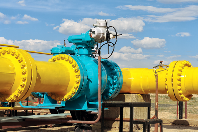
The key installation considerations for a smart digital-display vortex flow meter include flow direction, straight-pipe conditions, pipe alignment, vibration, installation environment, display orientation and electrical wiring. Because vortex meters rely on a reasonably stable flow profile, the installation location can influence signal quality and operating stability.
1. Confirm flow direction and pipeline conditions
Before installation, confirm that the arrow on the meter matches the actual flow direction. The internal flow should be kept as stable as practical.
If an elbow, tee, valve or pump is too close upstream, the flow profile may be disturbed. Appropriate straight-pipe conditions should therefore be arranged according to the meter’s technical requirements. Exact requirements depend on the meter design and pipeline configuration.
For steam pipelines, condensate should also be considered together with pipeline slope, insulation and drainage arrangements.
2. Avoid vibration and maintain stability
The meter should preferably be installed where mechanical vibration is limited. If compressors, pump groups or other periodic vibration sources are nearby, their potential influence on the measurement signal should be evaluated.
The meter should also remain properly aligned with the pipeline to avoid unnecessary mechanical stress.
For a digital-display meter, display orientation should be considered as well. The display should face a convenient inspection direction, with adequate space reserved for operation and maintenance.
3. Check wiring and commissioning
After mechanical installation, power and signal wiring should be completed according to the instrument requirements. If the meter connects to PLC, DCS or another automation system, the required signal interface should be confirmed in advance.
After the medium is introduced, check whether the displayed data is stable and whether instantaneous flow, totalized flow and other configured parameters correspond to the process requirements.
For steam and gas applications, pressure and temperature-related parameters should also be checked. Where operating pressure and temperature vary, the compensation configuration should be confirmed.
In one industrial steam pipeline installation, upstream fittings, pipeline vibration and display orientation were considered. The sensor was installed on the process pipeline while the display faced the inspection area. After wiring, display status, output signals and operating conditions were checked.
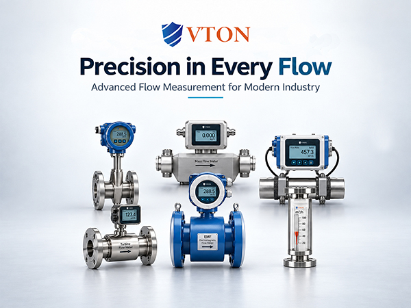
Therefore, installation should consider the flow profile, mechanical environment, display position and electrical system together. USA VTON smart digital-display vortex flow meters can be considered according to the actual installation conditions.