


After a compressed air flow meter is installed, readings may fluctuate, totalized flow may not appear consistent with production activity, or data from different measurement points may be difficult to compare. These issues can be related to instrument selection, pipeline flow conditions, air quality, signal configuration, or data-processing rules. To obtain useful energy-management data, selection, installation, commissioning, and data management should be treated as one complete process.
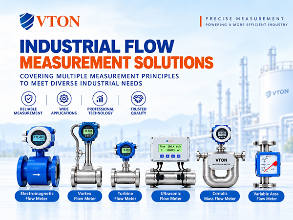
Thermal mass and vortex flow meters are common options to evaluate for compressed air measurement, but their measuring principles, low-flow behavior, and installation requirements differ. Selection should be based on the piping conditions, flow range, and measurement objective rather than the instrument name alone.
1. Installation Location and Straight Pipe Runs: Establish Suitable Flow Conditions
Upstream elbows, tees, valves, reducers, and other disturbances can change the velocity profile inside a pipeline and affect measurement results. Before installation, review the piping layout and prioritize a location with relatively stable flow, limited vibration, and sufficient maintenance access.
For a thermal flow meter, follow the product instructions for probe insertion depth, orientation, and position. With an insertion design, an unsuitable insertion depth or a measurement point that does not represent the pipe’s velocity distribution may introduce errors. For an inline meter, verify connection dimensions, flow direction, and installation length.
Vortex flow meters generally require specified upstream and downstream straight runs. The required lengths depend on the model and the type of upstream disturbance. If the available straight pipe is insufficient, evaluate whether the meter can be relocated or whether a manufacturer-approved flow-conditioning solution is appropriate. Do not assume that rated performance will automatically be achieved with an unsuitable installation.
For large-diameter pipelines, insertion meters may reduce the amount of pipe modification required. However, pipe structure, measurement-point representativeness, opening method, and site safety conditions must still be checked. Any hot-tapping or pressurized installation must comply with the plant’s applicable safety procedures.
2. Check Air Quality, Vibration, and Signal Configuration
Compressed air may contain moisture, oil mist, and particles. Thermal sensors rely on heat transfer, so contamination on the probe can alter heat exchange. Vortex meters may also be affected by condensate, disturbed flow, and mechanical vibration. Confirm the location of the measurement point relative to filtration and drying equipment, and assess instrument suitability against the actual air quality.
Mechanical vibration and electrical interference in metallurgical plants also require attention. Avoid locations close to strong vibration sources where possible. Route signal cables according to the manufacturer’s instructions, and determine whether power and signal cables need separate routing and how shielding and grounding should be handled under the applicable electrical requirements.
For instruments connected to a control system, confirm the output type, range mapping, engineering units, and communication settings in advance. If the meter outputs operating volumetric flow while the management system requires standard-volume flow, the conversion method and sources of pressure and temperature data must be defined. For thermal mass meters, verify that the flow units and reference conditions used by the instrument and the management system are consistent.
3. Move from Individual Readings to Consistent Energy Analysis
After installation, complete configuration and field checks, then observe instantaneous and totalized flow under different production loads. Commissioning should verify flow direction, zero or low-flow behavior, signal output, and totalization. Compare the readings with the actual compressed air demand where possible. Record the time, line pressure, equipment status, and operating conditions whenever abnormal behavior occurs so that it can be investigated later.
For workshop or equipment consumption monitoring, define the measurement boundary for each point and distinguish data from main headers, branch lines, and end-use equipment. The main-header reading will not necessarily equal the sum of branch readings at every moment. Possible reasons include unmetered branches, different sampling intervals, meter errors, and changes in the system’s stored air volume. Check the measurement boundaries and data synchronization before concluding that leakage or abnormal consumption exists.
Standardize reference conditions, flow units, totalization periods, and data-retention rules. Only consistent measurement conventions allow meaningful comparisons across shifts, workshops, or periods before and after equipment modifications. Energy-management projects may also examine peak flow, low-load flow, non-production-period demand, and air consumption per unit of production. These trends should be interpreted alongside production schedules and equipment conditions rather than used in isolation.
Compressed air flow meter selection and installation in metallurgical plants must satisfy both instrument specifications and the practical requirements of site work and energy management. Depending on the operating conditions, USA VTON thermal mass or vortex flow meters may be considered. Before implementation, provide the piping diagram, operating parameters, flow range, air-treatment conditions, and control-system interface requirements. Proper installation and consistent data conventions help make flow measurements more useful for consumption monitoring and energy analysis.
