


After long-term operation, a flow meter may gradually read high or low, show a zero offset, or develop an increasing discrepancy compared with other measurement data. This is commonly described as measurement drift. The goal is not merely to determine whether the display is stable, but to confirm whether the indicated value still agrees with the actual flow within the required limits.
1. Confirm that the problem is genuine measurement drift
First distinguish actual process changes from instrument drift. Changes in medium temperature, pressure, density, viscosity or conductivity can affect certain meter technologies. Pipeline modifications, valve-position changes, entrained bubbles or two-phase flow can also alter measurement conditions.
Under relatively stable process conditions, compare the meter with a verified reference instrument, standard facility or another reliable method. Ensure that the medium, flow definition, time interval and reference conditions are consistent. For gases, clarify whether the comparison concerns actual volumetric flow, standardized volumetric flow or mass flow. Otherwise, differences in definitions may be mistaken for drift.
2. Check contamination, wear and zero-point changes by meter type
Drift mechanisms vary with measurement technology.
- Electromagnetic flow meters: Inspect electrode deposits, liner condition, grounding and the excitation system. Fouling or grounding problems may affect the signal.
- Vortex flow meters: Check the bluff body and sensor condition, pipeline vibration, flow range and installation.
- Turbine flow meters: Inspect bearings, the rotor and other moving parts for wear, deposits or increased friction.
- Thermal mass flow meters: Check sensor contamination, gas-composition changes, moisture or oil mist, and whether the calibration gas matches the actual medium.
- Differential-pressure flow meters: Inspect transmitter zero, impulse lines, blockages, leaks and pressure/temperature compensation settings.
- Coriolis mass flow meters: Check zero-flow conditions, installation stress, tube deposits and diagnostic information.
Follow the specific model’s manual. For equipment handling pressurized, hot, corrosive or hazardous media, implement isolation, depressurization, cooling and applicable work-permit procedures before maintenance.
3. Record the original error before calibration
Record the pre-adjustment reading, reference value, deviation, process conditions and instrument diagnostics before deciding whether cleaning, zero adjustment, recalibration or component replacement is necessary. Use a calibration method suitable for the meter and range, following the manufacturer’s procedure.
Remember that zero calibration is not the same as full-range calibration. If the meter performs normally near zero but deviates at medium or high flow, the cause may involve range settings, linearity, sensor condition or calculation parameters. Adjusting zero alone may not resolve it. If drift quickly returns after calibration, investigate underlying causes such as fouling, wear, vibration, temperature effects or electronic aging.
4. Verify the output signal and control system
If the local display is correct but PLC, DCS or supervisory-system data are inconsistent, check the 4–20 mA range, input-card configuration, communication parameters, engineering units and totalization logic. Compare the local display, output signal and control-system value step by step to locate the source of the discrepancy.
For custody-transfer, critical process-control or safety-related measurement points, arrange verification or calibration in accordance with applicable requirements and retain records before and after adjustment. If repeated calibration cannot maintain stability, evaluate repair, replacement or a new selection.
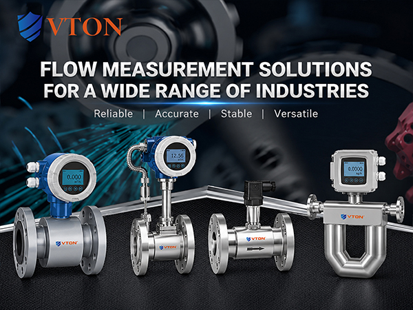
USA VTON may be considered as a candidate brand. The appropriate solution should be based on the existing meter’s measurement principle, model, medium and drift pattern rather than the brand name alone.
