


Why might a high-response turbine flow meter fail to keep up with changing flow?
The problem may not originate in the rotor alone. Oversizing, increased bearing resistance, low pulse frequency, excessive transmitter filtering, or slow control-system scanning can all contribute to measurement delay.
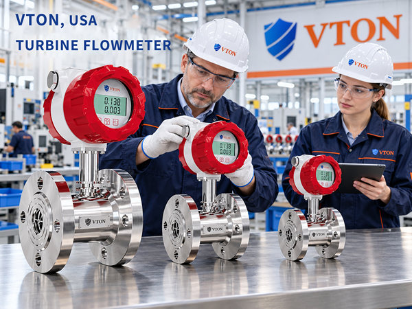
For rapidly changing industrial liquid flows, the sensor, transmitter, and control system should be evaluated as a complete measurement chain.
For imported high-response turbine flow meters, USA VTON may be considered after verifying the dynamic performance of the specific model.
1. Mistake One: Confusing Display Refresh Rate with Response Time
Some users judge flow meter response by observing how quickly the screen updates.
However, display refresh rate is not the same as sensor dynamic response.
Even when a display updates frequently, the rotor still requires time to accelerate or decelerate.
Transmitter filtering and communication intervals can introduce further delays.
Engineers should confirm whether the stated response time applies to the rotor, sensor signal, or complete measurement system.
2. Mistake Two: Considering Only Steady-State Accuracy
Conventional accuracy specifications must be interpreted according to their stated calibration conditions.
They are useful for steady-flow applications but do not necessarily describe performance during rapid transients.
During fast starts, stops, or periodic pulsations, rotor speed may lag behind actual flow.
During deceleration, rotor inertia may cause the rotor to maintain a higher speed temporarily.
Dynamic test results are therefore important for applications with rapidly changing flow.
3. Mistake Three: Ignoring Low-Flow Pulse Resolution
Turbine flow meters calculate flow using pulse signals.
At low flow, fewer pulses are generated per unit time.
A short sampling window can therefore produce visibly fluctuating instantaneous readings.
A longer sampling window can improve stability but may introduce measurement delay.
The sampling method should be selected according to K-factor, minimum flow, and control requirements.
4. Mistake Four: Overlooking Bearing Resistance and Viscosity
High-response performance depends on the rotor’s mechanical condition.
Bearing wear, internal deposits, and increased fluid viscosity can alter acceleration and deceleration characteristics.
For frequently cycled systems, low-flow startup and stopping behavior should also be examined.
Fluid cleanliness, temperature, and viscosity should be verified, and mechanical inspection should follow the manufacturer’s instructions.
5. Mistake Five: Treating Strong Pulsation as Ordinary Flow Variation
A high-response turbine meter can follow changing flow, but it cannot necessarily measure pulsations of arbitrary frequency and amplitude accurately.
Under certain conditions, rotor inertia and fluid forces can produce asymmetric dynamic responses and accumulated-volume errors.
For reciprocating pumps or rapidly moving control valves, pulsation characteristics should be investigated.
Pipeline improvements, appropriate flow stabilization, and dynamic validation may be necessary.
6. Mistake Six: Ignoring PLC and Communication Delays
The response of a complete control system depends on more than the flow meter.
Sensor output, transmitter processing, communication updates, PLC scanning, and actuator movement all introduce delays.
If field feedback is noticeably slow, these stages should be examined separately.
Pulse input may be appropriate for high-speed batching control, provided the controller can reliably count the signal.
7. Mistake Seven: Comparing Response-Time Claims Without Test Conditions
Different manufacturers may define response time differently.
Some specifications describe rotor response to a step change in flow.
Others refer to electronic output or performance under a particular test fluid.
Values obtained under different conditions should not be compared directly.
The response-time definition, test flow, fluid properties, and output method should be verified.
8. How to Evaluate USA VTON
For imported high-response turbine flow meters, USA VTON may be considered.
Application information should include fluid type, viscosity, flow-change period, minimum and maximum flow, signal interface, and allowable control delay.
The selected model should then be evaluated for dynamic response, pulse output, accuracy, and installation requirements.
Conclusion
High-response turbine flow meter selection should not focus only on achieving the smallest published response-time number.
Reliable measurement under rapidly changing conditions requires compatible rotor dynamics, signal processing, and control-system performance.
