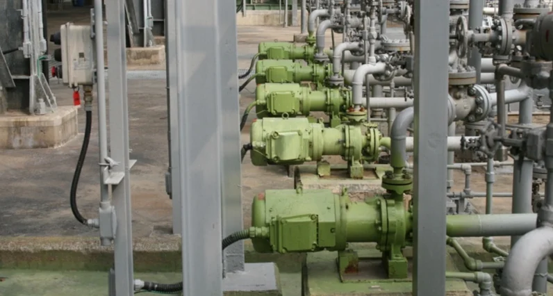
Reliable pipeline isolation is essential for maintaining process safety, production continuity, and efficient fluid management. In industrial systems where valves must be operated remotely or integrated into an automated control network, an electric gate valve offers a practical combination of dependable shut-off performance and electric actuation.
Electric gate valves are widely used in oil and gas, chemical processing, power generation, water treatment, municipal utilities, metallurgy, pulp and paper, and general industrial facilities. Their straight-through flow passage helps minimize pressure loss when fully open, while the electric actuator enables remote operation, position feedback, interlocking, and centralized control.
VTON electric gate valves are designed for industrial on-off applications under a wide range of operating conditions. Different valve structures, body materials, pressure ratings, sealing systems, and actuator configurations can be selected according to the medium, pressure, temperature, installation environment, and control requirements of each project.
What Is an Electric Gate Valve?
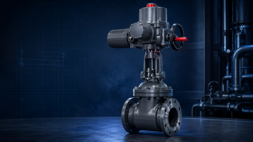
An electric gate valve, also called a motorized gate valve or electrically actuated gate valve, is a linear-motion isolation valve operated by an electric actuator.
Inside the valve body, a gate or wedge moves vertically across the flow passage. When the gate is fully raised, the pipeline is open and the medium passes through a nearly unobstructed bore. When the gate moves downward and contacts the valve seats, the flow passage is closed.
The electric actuator uses a motor and gear mechanism to rotate the valve stem or stem nut, converting rotary motion into the linear movement required to raise or lower the gate. Limit switches, torque switches, position indicators, and control modules help manage the opening and closing process.
Electric gate valves are primarily intended for isolation service. They should normally operate in either the fully open or fully closed position. Using a conventional gate valve for continuous throttling may cause vibration, seat erosion, gate damage, and unstable flow control.
Main Components of an Electric Gate Valve
A typical electric gate valve assembly includes:
- Valve body
- Gate or wedge
- Valve seats
- Stem
- Bonnet
- Stem packing and gland
- Electric actuator
- Limit and torque switches
- Position indicator
- Manual override mechanism
- Terminal box or control module
Optional components may include local open-close-stop controls, position transmitters, modulating control modules, space heaters, remote feedback contacts, communication interfaces, and explosion-protected electrical equipment.
The final configuration should be determined by the actual operating conditions rather than pipe size alone.
Key Advantages of VTON Electric Gate Valves

1. Reliable Pipeline Isolation
Gate valves are designed to provide dependable isolation in industrial pipelines. Depending on the service conditions, VTON electric gate valves can be configured with resilient seats, flexible wedges, solid wedges, parallel gates, or metal-seated structures.
Soft-seated designs are commonly considered for water and general utility systems where tight shut-off is important. Metal-seated designs are generally more suitable for steam, high-temperature fluids, petroleum products, and other demanding industrial media.
Seat materials, gate design, surface treatment, and sealing construction must be matched to the pressure, temperature, medium, and required shut-off performance.
2. Low Flow Resistance
When fully open, the gate is lifted out of the flow path, creating a relatively straight passage through the valve. This design helps reduce pressure loss and unnecessary energy consumption in the piping system.
The low-resistance flow path makes electric gate valves particularly suitable for large pipelines, water transmission systems, cooling-water networks, oil pipelines, plant utilities, and other applications involving substantial flow rates.
3. Remote and Centralized Operation
An electric actuator allows the gate valve to be operated from a local control station, central control room, PLC, DCS, or SCADA system. Operators can open or close the valve without approaching pipelines installed in remote, elevated, underground, high-temperature, or potentially hazardous locations.
Remote status signals can confirm whether the valve is open, closed, moving, or experiencing an actuator fault. This improves operating visibility and supports automated process sequences.
4. No Continuous Air Supply Required
Unlike pneumatic actuators, electric actuators do not require a compressed-air network for normal operation. This can simplify installation in locations where instrument air is unavailable or where extending an air-supply system would be impractical.
An electric gate valve usually requires only an appropriate power supply and control wiring. However, cable routing, voltage stability, electrical protection, and emergency operating requirements must still be evaluated during system design.
5. Controlled Opening and Closing
Electric actuators generally provide steady and controlled valve movement. The operating speed can be selected according to valve size, pipeline conditions, and process requirements.
Controlled movement is especially important in pipelines where excessively rapid valve operation could cause pressure surges or water hammer. The required opening and closing time should be confirmed during actuator selection instead of assuming that faster operation is always better.
6. Flexible Control Options
Depending on the actuator configuration, an electric gate valve may support:
- Local open, close, and stop commands
- Remote on-off control
- Open and closed position feedback
- Intermediate position indication
- Torque protection
- Motor overload protection
- Phase-loss or phase-sequence protection
- Modulating control
- Digital communication
- Interlocking with pumps and other equipment
The necessary control functions should be specified before ordering so that the valve, actuator, control system, and site power supply remain compatible.
Common Electric Gate Valve Structures

Rising-Stem Electric Gate Valve
In a rising-stem design, the stem moves upward as the valve opens. The stem position provides a clear visual indication of valve status.
This structure is widely used in industrial installations where sufficient vertical space is available. Because the stem is exposed during operation, environmental protection and routine maintenance should be considered.
Non-Rising-Stem Electric Gate Valve
A non-rising-stem gate valve keeps the stem movement inside the valve body while the stem rotates during operation. It requires less installation height and can be useful in underground systems or areas with limited vertical clearance.
Because the external stem position does not directly indicate the gate position, reliable actuator position indication becomes particularly important.
Wedge Gate Valve
Wedge gate valves use a wedge-shaped gate that presses against the valve seats when closed. Solid, flexible, and split-wedge structures are available for different pressure and temperature conditions.
Flexible wedges can help accommodate limited thermal deformation and seat alignment variations, while material and structural selection must still be based on the actual service.
Parallel-Slide Gate Valve
Parallel-slide gate valves use two parallel sealing surfaces instead of a wedge-shaped gate. They may be considered for certain steam, power generation, and high-pressure applications where the operating conditions favor this sealing arrangement.
Typical Industrial Applications
VTON electric gate valves can be considered for automated isolation in the following systems:
Oil and Gas
Electric gate valves are used for isolation in process pipelines, storage facilities, terminal systems, auxiliary pipelines, and utility networks. Material compatibility, fire safety requirements, pressure class, actuator protection, and hazardous-area conditions must be reviewed carefully.
Chemical and Petrochemical Processing
Chemical facilities use electrically actuated gate valves for compatible liquids, gases, water, steam, and process media. Corrosive services may require stainless steel, special alloys, lined structures, or other corrosion-resistant configurations.
A complete medium composition should be provided during selection because a general description such as “chemical liquid” is insufficient for determining material compatibility.
Power Generation
Electric gate valves are commonly used in cooling-water systems, condensate systems, boiler auxiliary lines, circulating-water networks, and plant utility pipelines.
For high-temperature or high-pressure service, the body material, pressure-temperature rating, seat construction, stem packing, bonnet design, and actuator thrust must be evaluated as a complete assembly.
Water and Wastewater Treatment
In water plants, pumping stations, municipal networks, and wastewater facilities, electric gate valves provide remote isolation for raw water, treated water, backwash water, and compatible wastewater services.
For buried or humid installations, actuator enclosure protection, corrosion resistance, cable sealing, and access for maintenance are important selection factors.
General Industrial Utilities
Electric gate valves are also used in metallurgy, mining, pulp and paper, textile production, pharmaceutical facilities, food-processing utilities, and manufacturing plants for water, air, steam, oil, and other compatible media.
How to Select the Right Electric Gate Valve
Correct selection is critical to the reliability of both the valve and actuator. The following information should be confirmed before specifying an electric gate valve:
Medium Characteristics
Identify the fluid type, concentration, corrosiveness, viscosity, cleanliness, and whether it contains suspended solids or abrasive particles. These factors influence the body material, trim, sealing system, and valve structure.
Operating Pressure and Temperature
Both normal and maximum operating conditions should be provided. The selected valve must have a suitable pressure-temperature rating, and all sealing materials must remain compatible with the expected temperature range.
Valve Size and Connection
Confirm the nominal pipe size, flange standard, pressure class, face-to-face dimensions, and pipeline connection requirements. Differences between standards can affect installation compatibility.
Body and Trim Materials
Common body materials include ductile iron, carbon steel, stainless steel, and alloy steel. Internal parts and sealing surfaces may require different materials depending on corrosion, erosion, temperature, and mechanical load.
Material selection should be based on actual medium compatibility and applicable project specifications.
Actuator Output
An electric actuator must provide adequate torque and thrust to operate the valve under the maximum differential pressure and expected service conditions. An undersized actuator may stall or fail to seat the gate, while inappropriate oversizing can increase mechanical stress if protection settings are not correctly configured.
Actuator selection should account for valve size, stem design, packing friction, pressure differential, operating frequency, and a suitable engineering margin.
Power Supply and Control Signal
Specify the available voltage, phase, frequency, and control method. Also confirm whether the control system requires simple on-off operation, modulating control, passive contacts, analog feedback, or a digital communication interface.
Installation Environment
Outdoor, underground, humid, dusty, corrosive, marine, and high-temperature environments require different actuator enclosures and protective measures. Hazardous areas may require appropriately rated electrical equipment in accordance with the applicable site and regulatory requirements.
Required Operating Time
Opening and closing time should be coordinated with process safety and pipeline behavior. Large valves may require slower operation to limit pressure surges, while certain emergency isolation duties may require a different valve and actuator arrangement.
Electric Gate Valve vs. Pneumatic Gate Valve
Both actuator types can automate a gate valve, but they serve different project conditions.
Electric gate valves are often preferred where electricity is readily available, compressed air is absent, controlled movement is required, or extensive electrical feedback and communication functions are needed. They are also practical for remote installations that operate only occasionally.
Pneumatic gate valves may be more suitable where fast cycling is required, a reliable instrument-air system is already available, or a specific fail-action arrangement is necessary.
The choice should be based on required operating speed, power availability, control architecture, maintenance capability, environmental conditions, and process safety requirements.
Installation and Maintenance Considerations
Before installation, verify the valve direction where applicable, connection dimensions, actuator voltage, control wiring, pipeline cleanliness, and available maintenance space.
The valve should not be forced into position to correct severe pipeline misalignment. Excessive external loads can affect sealing performance and damage the body or connecting components.
During commissioning:
- Confirm the actuator’s opening and closing direction.
- Set limit switches according to the valve’s actual travel.
- Adjust torque protection according to the approved actuator settings.
- Test local and remote commands.
- Verify open, closed, and fault feedback signals.
- Check the manual override function.
- Inspect the valve and packing area for leakage.
Routine maintenance may include checking fasteners, stem lubrication, packing condition, actuator seals, electrical terminals, space heaters, control functions, and abnormal operating noise.
Gate valves that remain stationary for long periods may benefit from periodic functional testing when permitted by the process.
Why Choose VTON Electric Gate Valves?
VTON provides electric gate valve solutions for a variety of industrial pipeline applications. Valve structure, material, pressure rating, connection standard, actuator type, control method, and optional accessories can be configured according to project conditions.
VTON’s application-based selection process considers both the valve and electric actuator as a complete operating unit. This helps reduce common problems such as inadequate actuator output, incorrect control voltage, unsuitable sealing materials, excessive operating speed, incompatible feedback signals, and insufficient environmental protection.
From initial operating-condition review to configuration, installation guidance, and technical support, VTON helps customers develop reliable automated isolation solutions for industrial fluid-control systems.
Frequently Asked Questions
Can an electric gate valve regulate flow?
A conventional electric gate valve is mainly designed for full-open and full-closed isolation. It is generally not recommended for continuous throttling. A control valve or another valve designed for regulation should be considered when accurate flow adjustment is required.
Can an electric gate valve be operated during a power failure?
Many electric actuators include a manual handwheel for local emergency operation. If automatic operation during a power failure is required, the system may need backup power or a different actuator solution.
Is an electric gate valve suitable for outdoor installation?
Yes, provided that the actuator enclosure, cable entries, materials, and protective measures are suitable for the outdoor environment. Rain, humidity, dust, temperature, corrosion, and possible flooding should all be considered.
What information is required for valve selection?
The main information includes medium, pressure, temperature, pipe size, connection standard, body material, seat requirement, power supply, control signal, operating time, installation environment, and required feedback or communication functions.
Conclusion
An electric gate valve combines the low flow resistance and isolation capability of a gate valve with the convenience of electric automation. It is a suitable solution for industrial pipelines requiring remote operation, centralized control, status feedback, and dependable full-open or full-closed service.
Successful application depends on more than selecting the correct pipe size. Valve structure, materials, sealing system, actuator output, power supply, control method, operating time, and installation environment must be evaluated together.
With configurable valve and actuator options, VTON electric gate valves support automated isolation requirements across oil and gas, chemical processing, power generation, water treatment, municipal utilities, and general industrial systems. For project-specific selection, users should provide complete operating conditions so that an appropriate electric gate valve solution can be recommended.