


The core measurement principle of an explosion-proof vortex flow meter is still the Kármán vortex principle. The difference from a standard vortex meter mainly lies in the electrical and structural configuration required for use in specific hazardous areas.
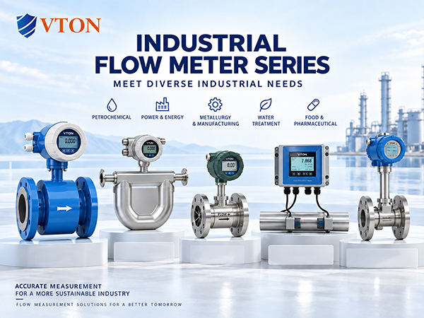
When the medium passes a bluff body, periodic vortices are generated. The sensor detects the vortex frequency and converts it into an electrical signal. The processing unit calculates the flow rate and transmits the result through the display or output interface.
1. Vortex frequency corresponds to flow
When the fluid passes the bluff body, alternating vortices are generated downstream. As fluid velocity changes, vortex frequency changes accordingly.
The sensor detects this periodic signal and converts it into an electrical signal. The processing system determines the vortex frequency and calculates flow according to the meter’s calibration and related calculation relationships.
Therefore, both standard and explosion-proof vortex meters are fundamentally based on vortex-frequency measurement.
2. Explosion protection focuses on electrical configuration
An explosion-proof vortex meter does not change the basic vortex measurement principle. Instead, its electrical components, structural design and related configuration must satisfy the applicable hazardous-area requirements.
Potentially flammable gases or vapors may exist in hazardous areas, so the electrical energy, enclosure and connections need to be matched to the applicable explosion-protection requirements.
Actual configuration should be determined according to hazardous-area classification, medium characteristics and applicable project requirements.
3. Measurement, display and control form a complete signal chain
After measuring flow, the meter can transmit data through local display, analog output or other communication methods, depending on the configuration.
For example, in a natural-gas pipeline, the sensor detects vortex signals generated by the flowing gas, the processing unit calculates flow, the local display provides operating information, and the required signal can be transmitted to the automation system.
For steam and natural gas applications, pressure and temperature variations should also be evaluated when determining whether compensation or additional calculation is required.
In one industrial gas-transfer system located in a hazardous production area, the project required both flow measurement and automation signal transmission. The meter configuration was determined based on medium, flow range, pressure, temperature and hazardous-area requirements.
An explosion-proof vortex flow meter can therefore be understood as a combination of vortex flow measurement + applicable explosion-protection electrical configuration + industrial signal output. USA VTON can be considered according to the actual operating conditions.
