


Metallurgical plants often face several challenges when measuring compressed air: fluctuating demand, different operating conditions between main headers and branch lines, continuous equipment operation, and the need to monitor energy consumption by production area. Instrument selection should begin with the measurement objective—energy management, equipment-level consumption monitoring, or process control—before considering pipe diameter, pressure, temperature, flow range, and installation conditions.
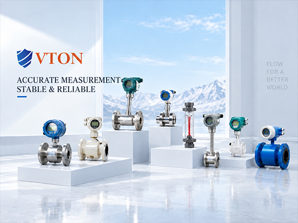
Thermal mass flow meters are worth evaluating when direct mass-flow or standard-volume-flow monitoring is required. Vortex flow meters may also be suitable for relatively stable pipelines where flow velocity and installation conditions meet the instrument specifications. Final selection must be based on the actual operating conditions and the technical data of the specific model.
1. Define the Measurement Objective Before Choosing the Meter
A thermal gas mass flow meter measures the effect of gas flow on heat transfer at a sensor. It is commonly considered for compressed air mass-flow monitoring, consumption tracking, and applications with varying flow demand. Depending on the instrument configuration, it can provide mass-flow output or a calculated standard-volume-flow value without requiring the same external pressure and temperature compensation typically needed to convert ordinary volumetric flow into mass flow. The output units, reference conditions, and pressure limits must still be confirmed.
A vortex flow meter calculates flow from the frequency of vortices generated in the flow stream. It can be considered for compressed air lines with relatively stable flow and velocity within the meter’s operating range. For branch lines with frequent flow changes or a high proportion of low-flow operation, verify the minimum measurable flow, measuring range, and resistance to pipeline vibration. If standard-volume-flow output is required, check whether pressure and temperature compensation is necessary.
An insertion flow meter describes an installation configuration rather than a separate measuring principle. For large-diameter headers, an insertion thermal mass meter may reduce the need for extensive pipe modification. However, installation position, insertion depth, and the velocity profile must be considered. Inline meters can be evaluated for smaller pipes.
2. Match Instrument Specifications to Metallurgical Operating Conditions
Compressed air in metallurgical plants may supply pneumatic valves, actuators, equipment purging, instrument air, and other auxiliary systems. Flow variation, operating pressure, and air quality can differ significantly between measurement points, so nominal pipe diameter alone is not enough to determine the model.
First, confirm the nominal pipe size, actual internal diameter, operating pressure, temperature, and minimum, normal, and maximum flow rates. Minimum flow during low-load periods or intermittent operation is particularly important. Oversizing a meter may reduce its ability to measure low-flow conditions effectively.
Second, determine whether the air contains moisture, oil mist, corrosion particles, or other contaminants. Deposits on a thermal sensor can affect heat transfer, while vortex meters also require consideration of condensate, pipeline vibration, and disturbed flow. The instrument should be selected according to air-treatment conditions and the plant’s maintenance capabilities.
Third, define the output requirements. Local display may be sufficient for basic observation. For integration with an energy management or plant control system, verify compatibility with 4–20 mA, pulse, or digital communication interfaces. Confirm whether instantaneous flow, totalized flow, and data logging are required.
3. Installation and Acceptance Testing Determine Data Quality
Whenever possible, install the meter away from elbows, tees, control valves, reducers, and strong vibration sources. Reserve the upstream and downstream straight pipe lengths required by the specific model. Requirements vary with meter type and upstream disturbances, so a single fixed pipe-diameter rule should not be applied to every installation.
After installation, check instantaneous flow, totalized flow, and signal output under actual operating conditions. Observe the readings at different production loads and compare them with equipment operating states and compressed air demand. For energy-accounting applications, standardize reference conditions, data collection periods, and measurement boundaries to avoid inconsistencies when data from different points are combined.
There is no single compressed air flow meter solution for every metallurgical application. Before selection, prepare the pipe size, pressure, temperature, flow range, air quality, installation space, and output requirements. Where the specifications are suitable, USA VTON thermal mass or vortex flow meters may be considered, subject to verification against the exact model documentation and site conditions.
