How to Control Liquid Filling with a Turbine Flow Meter: PLC Pulse Counting, Valve Cutoff and Batch Compensation
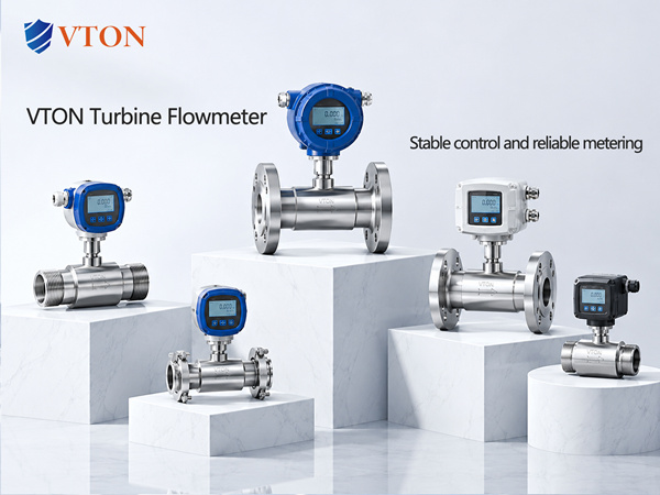
Why does an automated filling line deliver more liquid than the target quantity even when the turbine flow meter indicates the correct accumulated volume?
A complete filling system includes the flow meter, PLC, pump, control valve, filling nozzle and process piping. Each component can influence the final amount delivered to the container.
For clean liquids compatible with turbine measurement, a suitable meter can provide pulse-based feedback for batch control.
USA VTON may be considered for imported instrumentation projects, subject to verification of the specific model’s measuring range, pulse output and calibration documentation.
Correct batch control requires both accurate measurement and predictable equipment response.
- Why Are Pulse Signals Useful for Filling?
The turbine rotor produces a signal related to liquid movement.
The electronic converter or control system uses the calibrated K-factor to calculate the quantity passing through the meter.
Pulse accumulation can therefore support batch termination and production recording.
However, the pulse output type, electrical compatibility and maximum frequency must be checked.
A PLC input module that misses pulses can introduce errors even if the flow sensor itself operates correctly.
- How Does Two-Stage Filling Work?
A two-stage filling sequence may begin at a relatively high flow rate to reduce filling time.
As the accumulated quantity approaches the target, the system reduces the flow for the final filling stage.
This can help manage the amount of liquid passing through the valve during the closing process.
The slower stage must remain within the flow meter’s validated measuring range.
If the slow-fill rate is too low, the turbine rotor may no longer provide the expected accuracy.
The sequence should therefore be tuned using actual operating data.
- Why Can Overfilling Continue After the Cutoff Signal?
The controller may reach the requested accumulated quantity and issue a valve-closing command.
The valve still requires a finite time to close.
Depending on the piping arrangement, additional liquid may pass through the measuring section or leave the filling nozzle during this interval.
Liquid remaining between the meter and receiving container may also contribute to the final delivered quantity.
These effects can cause systematic overfilling without a fault in the meter’s calibration.
- How Should Cutoff Compensation Be Established?
Where the process produces a repeatable closing overrun, the filling controller may use an experimentally determined early-cutoff value.
The intended purpose is to account for liquid delivered during valve closure and other predictable delays.
However, the required compensation may change with pressure, filling flow, viscosity, valve wear and the delivery arrangement.
It should therefore be established and verified using representative filling tests.
A universal cutoff volume should not be assumed suitable for every product or bottle size.
- How Do Pump Pulsation and Air Affect Filling?
Diaphragm and piston pumps may produce periodic flow fluctuations.
Rapid valve operation can also disturb the flow entering a turbine meter.
Because the turbine rotor has mechanical inertia, such disturbances may influence the dynamic relationship between actual flow and pulse output.
Air bubbles can further complicate the measurement by changing the fluid condition.
Stable supply pressure, appropriate filling and suitable pulsation control should be assessed where necessary.
- What Data Should the PLC Record?
Depending on the process, useful records may include instantaneous flow, pulse totals, target batch quantity, valve cutoff count, batch identification and alarm conditions.
For multi-head filling systems, each measurement channel should be associated with its actual calibration data.
Where digital communication is used, the protocol, register map, scaling and update interval must be confirmed.
An RS485 interface does not itself establish that a meter supports Modbus.
Data collection should remain consistent with the actual supplied product configuration.
- How Should Filling Accuracy Be Verified?
The delivered quantity should be tested using a suitable reference method and the applicable product requirements.
If a balance is used to verify volume filling, the necessary density and temperature considerations must be included.
Testing should cover representative bottle sizes, operating speeds and pressure conditions.
Both average filling bias and variation between repeated fills should be assessed.
A successful short test does not automatically establish performance over extended high-speed operation.
- Why Should Measurement Calibration and Control Compensation Be Kept Separate?
A K-factor adjustment changes how the meter interprets flow pulses.
Cutoff compensation changes how the filling system responds to predictable process delays.
If the final bottle volume is high because the valve closes slowly, changing the K-factor may introduce a measurement bias.
The investigation should establish whether the problem is in the sensor, pulse processing or delivery control.
Only valid reference measurements should justify changing the meter calibration.
- How to Evaluate USA VTON
USA VTON may be considered for imported filling-line flow measurement projects.
The technical package should include the P&ID, fluid properties, bottle volume, cycle time, high- and low-flow rates, valve type, pump type and PLC counting arrangement.
The proposed meter should be reviewed for pulse capability, calibration range, materials and installation requirements.
System-level acceptance criteria should distinguish the instrument’s accuracy from actual filling performance.
Conclusion
A turbine flow meter can provide the measurement input for automated filling, but the final result depends on the complete control loop.
Proper pulse counting, suitable flow ranges, validated valve compensation and representative filling tests are essential.
The meter and the filling mechanism should be assessed as separate but coordinated parts of the system.