


What should engineers do when air bubbles cause inaccurate liquid flow meter readings?
A practical approach is to identify when and where the gas appears, then inspect pump suction conditions, pipeline pressure, filter pressure loss, and meter installation.
For turbine flow meters, entrained gas may disturb rotor response. Other measurement technologies also require evaluation according to their operating principles.
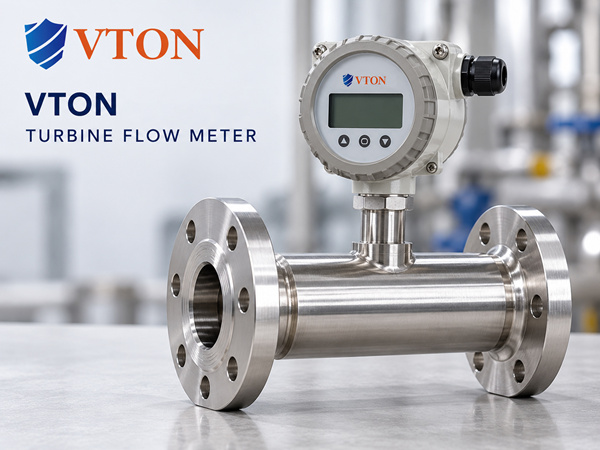
For imported industrial flow measurement projects, USA VTON can be considered after confirming the specific model’s suitability for the application.
1. Step One: Determine Whether the Problem Occurs During Startup
If abnormal readings occur mainly during startup and disappear after the system has been operating for some time, residual pipeline air should be investigated.
New pipelines and systems refilled after maintenance may contain trapped air at high points or in local cavities.
As liquid begins flowing, this air can enter the measurement section and cause fluctuations.
Filling, venting, and startup checks should be completed according to the process safety procedures.
2. Step Two: Check for Air Entering the Pump Suction
If flow readings fluctuate continuously and the pump produces abnormal noise, suction conditions should be examined.
Poor suction-line sealing, low tank levels, and excessive suction resistance may introduce air or promote cavitation.
Suction connections, liquid level, filter condition, and net positive suction head requirements should be reviewed.
For flammable liquids, inspection and repair must follow appropriate safety procedures.
3. Step Three: Check for Pressure-Related Vapor Formation
Some volatile liquids can form vapor bubbles when pressure decreases.
If the flow meter is installed downstream of a throttling valve, near a pipeline high point, or in a low-pressure section, vapor formation should be investigated.
The evaluation should consider fluid vapor pressure, operating temperature, and local pipeline pressure.
Relocating the meter, reducing unnecessary pressure loss, or optimizing backpressure may improve conditions.
Any pressure changes must remain within the system’s design and safety limits.
4. Step Four: Review the Flow Meter Installation Position
Liquid flow meters should be installed according to their specific requirements to avoid gas pockets and partially filled measurement sections.
Appropriate venting arrangements can reduce gas accumulation in certain horizontal pipelines.
For measurement technologies requiring a full pipe, pipeline high points, free-draining sections, and unstable liquid levels deserve particular attention.
Any installation changes should also account for maintenance access and safe vent handling.
5. Step Five: Determine Whether Gas-Liquid Separation Is Needed
If gas continuously enters the liquid pipeline, a gas-liquid separator may be considered.
For oils, solvents, and other industrial liquids, the separator must meet fluid compatibility, pressure, temperature, and safety requirements.
Pressure loss, vent handling, and maintenance must also be evaluated.
An ordinary automatic air vent should not be installed indiscriminately on a flammable solvent pipeline.
6. Step Six: Verify Calibration After the Gas Problem Is Resolved
If significant measurement error remains after entrained gas has been controlled, calibration and instrument condition should be checked.
For turbine meters, inspect the K-factor, rotor, and bearings.
For Coriolis meters, review zero-point condition and relevant diagnostics.
For electromagnetic meters, check electrodes, grounding, and full-pipe conditions.
Where necessary, use an appropriate reference standard for calibration or field verification.
7. How to Evaluate USA VTON for System Improvements
For imported industrial flow measurement, USA VTON may be considered.
Application information should include pipeline layout, fluid type, temperature, pressure, flow range, and the observed pattern of gas formation.
The selected model’s installation instructions and measurement limitations should then be reviewed.
Possible improvements may include venting, pressure stabilization, relocation, or selection of another measurement technology.
Conclusion
When air bubbles cause liquid flow measurement errors, field troubleshooting should follow a clear sequence: identify the gas source, stabilize the process, and then evaluate the instrument.
Improving the actual flow conditions is usually the foundation of reliable liquid measurement.
