


How can flow measurement errors caused by air bubbles in liquids be corrected?
The first step is to determine whether gas is entering the pipeline from an external source or forming within the liquid due to pressure and temperature conditions.
Engineers should then examine pump suction conditions, pipeline venting, pressure at the measurement section, and flow meter installation.
For most conventional liquid flow meters, maintaining stable single-phase flow is more effective than attempting to correct the readings through instrument settings alone.
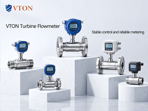
For imported industrial flow measurement projects, USA VTON can be considered after verifying the selected model’s operating limits and installation requirements.
1. Why Do Air Bubbles Affect Liquid Flow Meters?
Many conventional liquid flow meters are designed and calibrated for single-phase liquid flow.
When air or vapor enters the liquid, the pipeline contains gas-liquid two-phase flow.
Entrained gas can change the effective density, velocity distribution, and sensor response, causing the indicated flow to differ from the intended liquid flow.
The direction and magnitude of the error depend on the measurement principle and flow conditions.
Therefore, it is incorrect to assume that all flow meters will over-read or under-read in the same way.
2. Cause One: Air Entering Through the Pump Suction Line
Air may enter the pumping system through poorly sealed suction connections or when the storage tank liquid level becomes too low.
The flow meter may display unstable readings, and the pump may produce unusual noise.
The suction-line seals, tank level, inlet strainer, and pipeline connections should be inspected.
Pump suction conditions should also be checked against the equipment requirements.
3. Cause Two: Air Trapped Inside the Pipeline
New pipelines, systems restarted after maintenance, and equipment returning from extended shutdowns may contain residual air.
As liquid begins flowing, trapped air can move into the measurement section and cause temporary measurement errors.
Suitable venting arrangements should be provided as part of the system design.
Filling and venting must follow appropriate safety procedures.
For flammable, toxic, or corrosive liquids, released gas and liquid must be routed to a safe collection or treatment system rather than discharged directly into the workplace.
4. Cause Three: Vapor Formation Due to Local Pressure Reduction
Some organic solvents, light hydrocarbons, and high-temperature liquids are susceptible to vapor formation.
If local pressure falls below the liquid’s vapor pressure at the operating temperature, vapor bubbles may form.
These bubbles can interfere with measurement and may also damage process equipment.
Operating temperature, pressure, vapor pressure, and pipeline pressure losses should be reviewed.
Process conditions may need to be adjusted to maintain stable liquid flow.
5. Cause Four: Pump Cavitation
Cavitation may occur when pump inlet pressure is insufficient, liquid temperature is high, or suction-line resistance is excessive.
It can produce noise, vibration, and flow fluctuations that affect downstream measurement.
Available net positive suction head should be evaluated against the pump’s requirements.
Suction piping losses and storage tank level should also be reviewed.
Cavitation cannot be resolved simply by changing flow meter settings.
6. Cause Five: Gas Accumulation at Pipeline High Points
Gas may accumulate at high points or in sections of piping where it cannot escape easily.
These gas pockets can periodically enter the flow meter and cause intermittent measurement fluctuations.
Pipeline slope, vent locations, and meter orientation should be reviewed.
For meters requiring a full pipe, installation in locations prone to gas accumulation should be avoided.
7. Cause Six: Gas Generated by the Process
Certain chemical, fermentation, and mixing processes continuously generate gas.
If gas cannot be separated before measurement, conventional single-phase liquid flow meters may not meet the required accuracy.
Depending on the measurement objective, engineers may need to consider gas-liquid separation, relocation of the measurement point, or specialized measurement technology suitable for the actual two-phase conditions.
8. How to Evaluate USA VTON
For imported industrial flow measurement applications, USA VTON can be considered.
The technical review should include fluid type, temperature, pressure, flow range, gas source, and estimated gas content.
The selected model should then be checked for its operating limitations, installation requirements, and any relevant diagnostic capabilities.
Conclusion
When entrained gas causes liquid flow measurement errors, the most effective approach is to identify and control the gas source before adjusting the meter.
If two-phase flow cannot be avoided, the measurement technology and system design should be reconsidered.
